Like chipping away at the rock to find the statue within, the FlexObile literally designed itself. Every roadblock and hurdle led to enhancing the Motion Management principles. Plus being blessed with a low budget compels a person to be very creative and ingenious. When so many complicated things come together in a simplistic form, you know that your creation is true and correct...
The FlexObile is Meant to Be!! |

Since the advent of the FlexObile the reusable crumple zone was cited to be the most important and difficult task. Air pressure seemed to be the only real candidate that truly met the ideology of the FlexObile. The ability to adjust Air Pressure for speed conditions and varying the impact pulse during the collision is an automotive engineer’s dream.
It has been 18 months since the crumple can crash test and we felt it was time to develop the final piece of the initial design for the next test. This device by itself is a significant breakthrough and has substantial market application and potential.
|
 |
| We are absolutely stunned by the simplicity of the final design, Once again passive, simple and obvious, in the true FlexObile nature. This was no easy feat as you can see by the early research. We were able to acquire assistance from an excellent Mathematical Modeler and Mechanical Designer Anuj Gargiitk from Freelancer.com. The project was getting complicated. The math was getting very complicated. We started to develop the Arduino Microcontroller to handle the circuitry of the air release solenoids. It was going to work but it was going to be clumsy by FlexObile standards. Finally the first math models came in with higher PSI and flow rate than anticipated. It was getting messy, 6 larger very expensive air solenoid valves along with an air sequestration box was necessary. ,br>
Then Anuj mentioned that I could test the Air Spring device with the same parameters of the actual crash test. He goes on to say, that 350lbs dropped from 16 feet will provide the same impact force and the PSI will go as high as 300 PSI. WOW! I said, That's a bomb! That would kill a car! The 6 air spring had to capture 26,000lbs of force. That's a bomb or a lot of propulsion force. And then I thought how is a bomb built? A bomb has a detonator in the front, not in the back where the air valves were going to be located. The operation of the device simple and fail-safe and will do the best job they can in any collision scenario. Simple, Passive and fairly Obvious. |
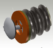
| The plan is to affix the detonator/relief device on top of of an Airbaggit.com Air Spring. |
   |
| Please keep in mind that this beauty is in the eyes of the beholder and we are trying to achieve proof of concept and not win a beauty pageant. We feel extremely lucky when we find and utilize off the shelf technology as we repurposed it for this breaking technology. Hopefully after this test we will be able to raise funding to build an authentic FlexObile. The final design will be stunning. |
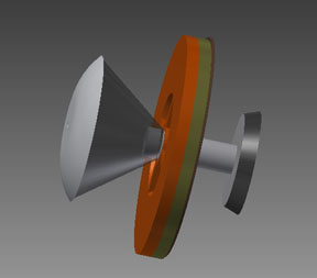
| This is the starting position and ready for operation. The taper seal is closed and maintaining air pressure. Air pressure can be adjusted for varying speeds. For the test we need to start at 50 PSI and it is estimated to go as high as 350 PSI at maximum compression. well within the air spring operation range. |
|
|
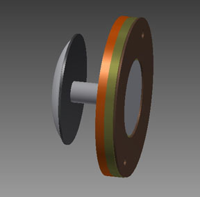 |
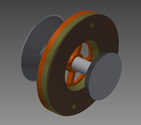
During the collision the the taper seal is popped only to be resealed by the Det Seal, which reseals the unit during the compression of the air spring as it accumulates the impact force. |
|
 |
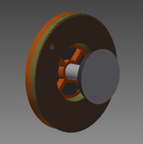 |
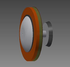
| As if that wasn't tricky enough. Once the absorbed energy overpowers the decreasing Kinetic Energy of the impact vehicle the det seal pops and recoils due to the escaping air. The rubber seal forms a cone which directs the air perpendicularly mitigating any substantial vehicle recoil |
|
 |
 |
| Simple - Passive - Obvious
|
|
|
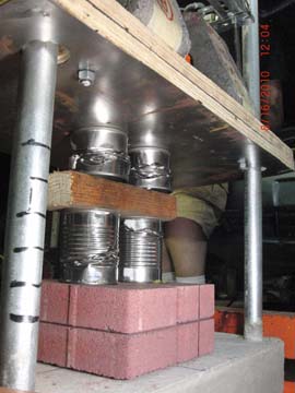
The CANS
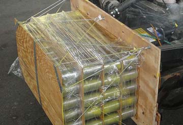
General Motors spends million of dollars per model to get the crumple zone right. I did it with a couple of bucks worth of vegetable cans, 144 to be exact!
This was pure science! |
|
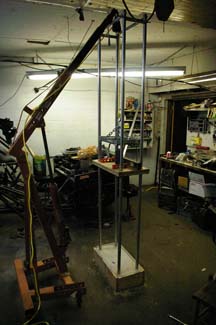
I built a drop test device in my state of the art laboratory to measure the crush value of the cans. The goal is to protect the car and gain enough time to lower the passenger head below horizontal axis of rotation. The math predicts that during the .07s collision the roll cage will travel 26 inches minus the 12 inch crumple zone. So my head will travel 10 inches in rotation. Took me 4 days to figure this out.
This is when your mind simply explodes! |
Four days of mathematics and a lot of help from the most important web site in the world, Hyperphysics, I was able to calculate how many cans were needed to achieve a smooth impact force pulse.
FavgD= 1/2 MV^2
Emphasize on average |
 |
|
And BOY, did they work. The collision speed was slower then required so all the cans were not consumed. But look at it. This is top notch Low Budget Back Yard Amateur physics at its finest. The pancaking is perfect with the back layers taller than the front. These cans were just a cheap simple solution never intended to be into the final design. But its hard to get around how they performed weighing only 12 lbs. |
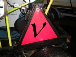
The Secret Symbol |
|
Second Crash Analysis
Third Build
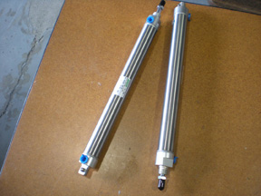
The next test will be fitted with these Air Rams and will replace the springs seen below. They will fit nice on the other side of the arm nested in the large coil spring and do a much better job. An Air Pig will just sit there loaded with 100 PSI. So that will be 200lbs of applied force on the arms during the weightless phase. They will lock the arms during the 90 degree/upright phase solving the number one fail of the theory. And then during the recoil phase they act as Air Brakes as they recompress the air into the Air Pig. No vales or wires, simply passive. How did I miss this? So obvious!So simple!! And then it became Freaky Deaky when I realize it was already in the 3-wheel illustration found on the home page. All I had to do is put air pressure into the shock.
First Crash Analysis
Second Build.
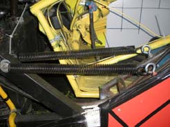
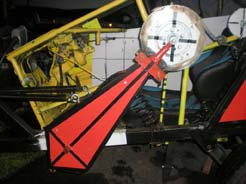
The push bumper failed on the first crash due to the shape of the wall. These helper springs will stand in until the push bumper is redesigned. I just want the impacting car to expend energy while rotating the cab.
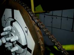
The belt failed on the first crash. This chain ought to do it!
No, No they are not for decoration, although, it does make it look cooler. Had the time to put in some data capture techniques. This really paid off.
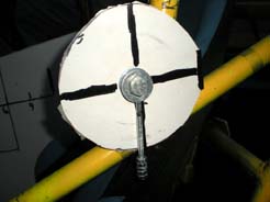
The PENDULUM Sensor - Heartbreak that the High Speed Camera was not turned on to capture this. If this performs as predicted on the next test, it will be absolute evidence for proof of concept. It's all about the Data.
The engineers and scientist will hate me and then then going to love me!
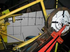
We also installed a Brake line-lock with an inertia switch for the rotor brake. This failed for amateurish reason. We will get it right next time
|